We have seen that objects do not move when the sum of the forces acting on them is zero. We can use this fact to find the conditions for "static equilibrium": the condition an object is in when there are forces acting on it, but it is not moving. The conditions for static equilibrium are easy to state: the sum of the (vector) forces must equal zero, and the sum of the torques must equal zero:
and
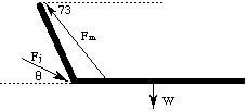
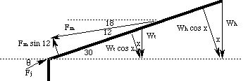
We will illustrate the use of these conditions with several examples from the human body. In each case, notice that the idea is to keep the relevent body part from moving in either the horizontal or vertical directions, and, once a convenient pivot is chosen, to keep the part from rotating around that pivot. Consider the following idealized arm:
We wish to find the forces required to hold the arm in place. The biceps muscle pulls upward with a force F m, and the upper arm exerts a force F j at the elbow joint, on the lower arm (ulna) to keep it in place. The biceps muscle is attached to the arm 4 cm from the elbow, and the ulna is 40 cm long. The mass of the ulna (and the object that the person is holding) is 14 kg, and causes a force W which is exerted downward by gravity at the midpoint of the ulna.
The point at which the force W is applied to the arm is the "center of gravity" or "center of mass", and for a uniform object (such as our idealized arm, and all of the idealized body parts we will be dealing with), the center of mass is in the "middle". Any rigid extended object can be treated as a point object of the same mass, located at the center of mass of the object.
The conditions for equilibrium for any system can be written as
| x | sum of forces left = sum of forces right |
| y | sum of forces up = sum of forces down |
| t | sum of torques counterclockwise = sum of torques clockwise |
Our first step is to identify the x (left and right) and y (up and down) components of each force. This means we need to construct a right triangle for each force, whose hypotenuse is the force vector and whose sides are horizontal and vertical:
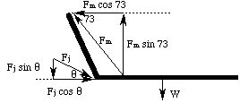
Note that we do not need to construct a triangle for W; it is already vertical, and has no horizontal component. The x and y equations are:
and
where W = m g.
The next step is to choose a pivot for the torque equations, and identify the force components which are perpendicular to the lever arm. For this system the ulna is the lever arm, and we choose the elbow for the pivot. Since F j acts at the pivot, its lever arm is zero, and hence so is its torque. The components of the forces which are perpendicular to the lever arm are F y and W, since in this example the lever arm is horizontal. The torque equation is:
From it we obtain F m = 717 N. Note that in the torque equation, we don't have to convert the lever arm lengths to meters; it is only necessary that the units match on both sides. Subtracting W from both sides of the y equation and dividing it by the equation for x, we obtain
This gives us a value of 69 degrees for q, and 587 N for F j.
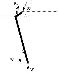
Now consider the compression of the vertabrae in the spine which occurs when a person leans over:
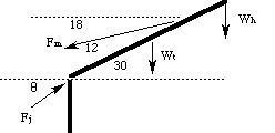
The muscle is attached two thirds of the way up from the bottom of the spine. The mass of the head and arms is 16 kg, and the mass of the torso is 32 kg. Note that in this case, the weight of the torso is applied at the center of mass, and the head is treated as a point mass at the end of the torso. Our first step is to identify the x and y components of the forces:
Here we have exaggerated the forces in order to clarify the drawing. The x and y equations for this problem are:
and
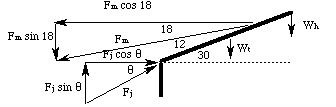
The next step is to find the components of the forces which are perpendicular to the lever arm. The lever arm is the spine, and the pivot is chosen at the base of the spine to eliminate F j from the torque equation. We now draw triangles (again exaggerating the forces) whose hypotenuse are the forces and whose sides are perpendicular and parallel to the lever arm:
At this point we don't know the angle x, but we do know that the triangles with the vertical weights are similar. Consider the following triangles:
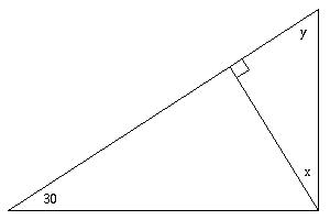
Since the sum of the angles in a triangle is 180 degrees, and these are right triangles, we know that
and
This implies that x = 30 degrees. The torque equation is then
where L is the length of the spine. Note that since it appears as a factor in every term in the equation for torque, the length of the spine is not important in this problem. Note also that the angle in the torque equation is different from that in the x and y equations. This is because the torque is computed from the component of the force which is perpendicular to the lever arm, which is not necessarily the y component! The solution for this problem is Fm = 1959 N, Fj = 2151 N and q = 30 degrees. If the person is picking up a 10 kg mass, W h is increased by 980 N and the new results are Fm = 2572 N, Fj = 2800 N and q = 29.1 degrees. Compare this result with that from the previous example, and you will understand why lower back pain is such a common malady!
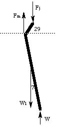
Finally, consider the forces on the hip as a person walks (the angle q is measured from the dashed horizontal line):
 (joint detail:)
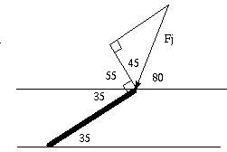
where the 35 degree angles are similar, the 35 and 55 degree angles are complementary and the 55, 45 and 80 degree angles are supplementary.
W is the person's entire weight (their mass is 70 kg), and W l is the weight of their leg (the mass of the leg is 18.5 % of their total mass, and its length is 80 cm). The pivot is taken to be at the point which the muscle acts (if we take the pivot to be at the joint, the angles are very messy; try it and see!). The length of the short "piece" at the top of the drawing is 7 cm, and it represents the distance between the point of attachment of the muscle to the femur and the point of contact with the hip joint. We obtain the following x and y equations:
and the torque equation
Using the same procedure as in the first problem, we find that F m = 1721 N, Fj = 2263 N and q = 76.8 degrees. Notice that the accuracy with which you reproduce these results depends, as in all of these problems, on the intermediate rounding you do.
In a situation when there is an injury, the angles and lever arms change in such a way as to reduce the force on the affected joint. Limping causes both forces to become vertical, with an approximately six degree shift in the femur toward the vertical:
Now the x components are all zero, and the remaining equations are:
and
This gives us the solution F m = 432 N and Fj = 991 N; we have reduced the force applied by the muscle by a factor of a three quarters, and the force on the joint by over half!
- Identify the force vectors;
- Use the various angle relationships (similar, alternate interior, complementary and supplementary) to identify the necessary angles;
- Draw a right triangle for each force, whose hypotenuse is the force and whose other sides are parallel to the x and y axes;
- Identify the x components of the forces as right or left, and the y components as up or down (if a force vector points left and up, the x component will be left and the y component will be up, etc.);
- Insert the expressions for the forces into the x and y equations;
- Choose a pivot for the torque equation;
- For every force which is applied at a nonzero distance from the pivot, draw a right triangle whose hypotenuse is the force and whose sides are parallel and perpendicular to the lever arm (the thing which that force could cause to rotate);
Note that if the lever arm is parallel to the x or y axis, you have already done this step, but be sure that you did not draw the triangle in such a way as to appear to have moved the point of application of the force!
- Identify the perpendicular components as contributing to counterclockwise or clockwise rotation of the lever arm;
- Insert those expressions into the torque equation and solve the problem!
The next chapter is about fluid dynamics.
If you have stumbled on this page, and the equations look funny (or you just want to know where you are!), see the College Physics for Students of Biology and Chemistry home page.
©1996, Kenneth R. Koehler. All Rights Reserved. This document may be freely reproduced provided that this copyright notice is included.
Please send comments or suggestions to the author.