While it may not seem obvious, we have dealt with circuits before: the cardiovascular system, centerpiece of our study of fluids, is completely analogous to the electrical circuits in which we are now interested. In fact, for every closed fluid system, there is an electrical circuit whose behavior is identical (up to conversion factors).
The heart develops a pressure difference which moves the blood through the system. Similarly, a battery (or other power supply) develops a voltage "potential difference" which moves electrons around the circuit (to a position of least energy). Thus a fluid pressure drop (energy per unit volume) corresponds to a potential difference, or "voltage drop" (energy per unit charge). Likewise, the flow rate of a fluid is analogous to the "current" in a circuit, which is the rate of movement of charge. Current is measured in C / s; this unit is called the "Ampere" (A).
Finally, Poiseuille's Law corresponds to "Ohm's Law" for electrical circuits. If we solve Poiseuille's Law for the pressure drop, and replace pressure drop by voltage and flow rate by current, we have
The quantity in parentheses has the characteristics of a "resistance": for a given voltage drop, a larger value of l results in less flow, while a larger value of r results in greater flow. In fact, the electrical analog of this fluid quantity is the resistance
where r is the "resistivity", L is the length of the conductor, and A is its radius. The fluid analog of the resistivity is essentially the ratio of viscosity to cross sectional area.
The unit of resistance is the Ohm (W), which is equal to a V / A. We formally write the current as
and Ohm's Law is
Ohm's law is in a sense more useful than Poiseuille's Law, for it is not restricted to long straight wires with constant current. This is essentially due to the order of magnitude of the size of the charge carriers. The speed of the charge carriers is much less than the speed of energy movement, just as the flow rate was much smaller than the speed with which pressure changes are propagated in a fluid. In the cardiovascular system, pressure changes propagated with the speed of sound (about 1500 m / s) while the blood move at less than 1 m / s. In a mammalian motor neuron, nerve impulses are propagated with a speed of 10 - 120 m / s, while the actual charge carriers move at less than 1 cm / s. In a wire, the speed of electrons is about 4 x 10 - 5 m / s, while the voltage changes propagate with (essentially) the speed of light (3 x 10 8 m / s in a vacuum)!
Fluid conservation principles are also applicable to electrical circuits. In the cardiovascular case, the pressure drop from the ventricle to the atrium was equal to the pressure at the ventricle; in the electrical case, the voltage drop around any closed loop is equal to the voltage of the source (battery or power supply) in that loop (or zero if there is no source in that loop). This is essentially the conservation of energy. In the cardiovascular case, the flow into a branch equalled the sum of the flows out; in the electrical case, the same is true for currents at a junction of conductors: conservation of charge. In the electrical parlance, these principles are known as "Kirchoff's Laws". These laws lead to the following rules for treating voltages and currents in series and parallel configurations:
These rules make possible the simplification of circuits with resistors in series or parallel by replacing them with equivalent resistors. Since voltage and resistance are proportional (in Ohm's Law), rule 1 tells us that we can replace two resistors in series by one whose resistance equals the sum of the original two. Since resistance and current are inversely proportional, rule 4 gives us the following equation for a resistor equivalent to two in parallel:
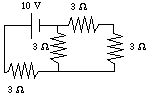
For example, consider the following circuit:
The two resistors on the right are in series. They can be replaced by an equivalent resistor:
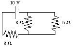
The two resistors on the right in this new equivalent circuit are now in parallel. They can be replaced by another equivalent resistor:
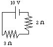
Note that the equivalent resistor has a SMALLER value than either of the originals; this is a general feature of resistors in parallel, since the current has alternate paths. Finally, the last two resistors are in series and can be replaced by one 5 W resistor.
Since the 5 W resistor is in parallel with the battery, the voltage drop across it is 10 V. Using Ohm's Law, the current through that resistor is 2 A. Now, working backwards, we know that the current across both of the above resistors is 2 A, since they are in series. This means that the voltage drop across the 2 W resistor is 4 V, and that through the 3 W resistor is 6 V. Note that the sum of the voltage drops is equal to the battery voltage. Returning now to the previous diagram, the voltage drop across the 2 resistors on the right are both 4 V (since they are in parallel). This means that the currents running through them are 1 1/3 A (for the 3 W) and 2/3 A (for the 6 W). Note that the sum of these currents is equal to the original current, as it should be. Returning now to the original diagram, the current through both right-hand resistors is 2/3 A, since they are in series, and so their voltage drops are both 2 V. Once again, the sum of the voltage drops is equal to the original voltage drop. The final voltages and currents are:
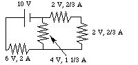
You can of course verify that Kirchoff's Laws are obeyed by these answers. In fact, since the solutions are unique, verification that Kirchoff's Laws are obeyed is an excellant check on your work. It is possible (and in general necessary) to use the techniques of linear algebra (solving multiple simultaneous linear equations expressing Kirchoff's Laws), but that will be unnecessary for our purposes.
The steps to solving one of these circuit problems are then:
The next section is on capacitors and RC circuits.
If you have stumbled on this page, and the equations look funny (or you just want to know where you are!), see the College Physics for Students of Biology and Chemistry home page.
©1996, Kenneth R. Koehler. All Rights Reserved. This document may be freely reproduced provided that this copyright notice is included.
Please send comments or suggestions to the author.